What Causes Performance Loss in Camlock Groove Coupling?
Views: 0 Author: Site Editor Publish Time: 2026-09-06 Origin: Site


Fluid and dry bulk transfer systems form the absolute backbone of modern industrial operations. When these critical pathways experience unexpected pressure drops or sudden leaks, they trigger immediate operational and financial disruptions. Engineers universally rely on cam and groove systems. They stand as industry standards for rapid, secure connections. However, performance degradation often reveals underlying symptoms. These include misaligned technical specifications, improper daily handling, or creeping material fatigue. Recognizing these subtle failure modes early separates highly reliable facilities from reactive ones.
Preventing costly downtime requires a strict evaluation of engineering tolerances. You must carefully assess the demanding operational environments where these components function. You also need to verify supplier credibility before installing any new parts. We will explore the mechanical root causes of performance loss. You will learn practical methods for specifying the correct materials. Finally, we will outline strict handling protocols. These steps maximize system lifespan and ensure workplace safety.
Key Takeaways
- Performance loss is primarily driven by gasket degradation, cam arm wear, and exceeding designated working pressure limits.
- Matching camlock groove coupling specifications strictly to the transfer medium (chemical, abrasive, temperature) prevents 80% of premature failures.
- Material selection directly dictates longevity; for example, an aluminium camlock coupling type a is highly efficient for specific lightweight fluid transfers but inappropriate for highly corrosive environments.
- Partnering with a fully vetted camlock groove coupling supplier ensures traceablity, verified pressure ratings, and adherence to safety standards.
1. The Business Cost of Coupling Inefficiency
Micro-leaks seem harmless during a casual facility walkthrough. However, they silently drain overall system efficiency every single minute. Pressure inconsistencies quickly stall automated production lines. They delay critical bulk transfers across large industrial facilities. You lose valuable engineering time diagnosing these hidden structural faults. Operational downtime inevitably cascades into missed delivery schedules and unhappy clients.
Furthermore, unexpected connection blowouts present severe safety hazards to personnel. This holds especially true in volatile sectors like oil and gas processing. Environmental contamination often triggers hefty compliance fines from regulatory agencies. Occupational hazards put your workforce at direct physical risk. A catastrophic mechanical failure demands immediate emergency response protocols. It forces entire facilities to halt operations entirely until repairs finish. Prioritizing reliable transfer connections protects both people and profit margins. You simply cannot afford to ignore minor pressure drops. Addressing them early prevents massive operational headaches later.
2. Primary Mechanical Causes of Performance Loss
Mechanical wear happens steadily over months of intense use. Several distinct failure points exist in every fluid transfer system. Understanding these fundamental mechanisms helps you prevent future catastrophic leaks.
Gasket Extrusion and Chemical Degradation
Elastomers play a vital role in sealing two metal faces. Incompatible elastomers swell or crack under intense fluid pressure. They chemically break down and extrude from the seating groove. Thermal cycling heavily impacts gasket memory over a long period. Extreme heat expands the rubber material rapidly. Cold temperatures cause it to shrink and harden unexpectedly. Eventually, the gasket loses its inherent ability to rebound. It fails to form a tight, dependable seal.
Cam Arm and Pin Fatigue
Repetitive manual coupling cycles degrade sturdy metal parts eventually. Operators often notice distinct visual wear patterns on the cam arms. Uncoupling frequently grinds internal metal surfaces together. Severe vibration induces loosening in high-kinetic industrial environments. Pumps send shockwaves down hoses directly into the locking mechanisms. The retaining pins holding the arms slowly warp over time. You lose the tight compression required for absolute safety. A loose arm allows pressurized fluid to escape instantly.
Abrasive Wear on the Groove
Dry bulk materials rub aggressively against internal metal surfaces. Grains, cement, and powders act exactly like sandpaper. Abrasive friction deforms the male adapter groove continuously. This physical deformation prevents a flush, 360-degree seal. The metal physically thins out after months of daily use. An uneven groove cannot mate properly against the rubber gasket.
Common Best Practices to Prevent Mechanical Wear:
- Inspect elastomeric gaskets visually before every high-pressure fluid transfer.
- Replace worn cam arms immediately upon noticing any mechanical looseness.
- Clean out adapter grooves regularly to prevent abrasive material buildup.
- Lubricate moving pins lightly to reduce metal-on-metal friction.
3. How Camlock Groove Coupling Specifications Dictate Reliability
Engineers must match parts precisely to their intended applications. Ignoring structural technical limits guarantees an eventual system failure. Following exact camlock groove coupling specifications prevents most sudden leaks. You must treat these parameters as strict operational boundaries.
Working Pressure Limitations
Every fitting carries a designated maximum working pressure. Pressure ratings decrease significantly as pipe diameters physically increase. A two-inch fitting usually handles much more pressure than a six-inch fitting. Fluid systems often experience sudden, violent pressure surges. Engineers call this destructive phenomenon hydraulic shock or "water hammer." Rapid valve closures send massive shockwaves backward through the fluid line. These dynamic spikes easily exceed the component's standard static rating. You must account for these dynamic surges during initial system design.
Material Selection and Application Mapping
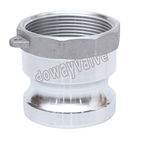
Material choice strictly dictates the operational lifespan of your fittings. Stainless steel handles harsh corrosive chemicals and extreme high pressure. Polypropylene suits agricultural uses and low-pressure municipal water lines. Let us look at a specific industrial use case. You might deploy an aluminium camlock coupling type a (Adapter x Female NPT) for lightweight transfers. It works perfectly for non-corrosive petroleum or bulk freshwater. We prioritize weight reduction heavily in these specific manual scenarios. Workers appreciate the lighter hoses during daily maneuverability. However, you should never use aluminum for highly corrosive acidic environments.
Thread and Dimension Standards
Global dimensional standards keep various industries safe and unified. You must strictly match MIL-C-27487 (now A-A-59326) military guidelines. Some modern facilities prefer adopting EN 14420-7 standards instead. Matching these exact codes prevents dangerous mismatched manufacturing tolerances. Budget parts often deviate slightly from strict dimensional codes. Even a single millimeter of variance ruins the compression seal.
Material Selection Guide for Fluid Transfers
| Housing Material | Optimal Industrial Application | Key Limitation to Watch |
|---|---|---|
| Stainless Steel (316) | Harsh chemicals, sanitary food lines, high pressure. | Heavy weight, higher initial procurement cost. |
| Aluminum | Petroleum, freshwater, lightweight manual transfer hoses. | Highly susceptible to corrosion from strong acids. |
| Polypropylene | Agricultural fertilizers, low-pressure fluids. | Weak resistance to extreme temperature changes. |
| Brass | Marine environments, non-sparking fuel transfers. | Softer metal deforms under extreme physical abuse. |
4. Operational Best Practices: Handling and Maintenance
Human error causes many industrial connection failures. Proper daily handling exponentially extends the life of every component. Your operational team needs highly clear maintenance protocols. Training your staff thoroughly mitigates most preventable damages.
Proper Connection Protocol
Operators sometimes use blunt force during tight connections. They mistakenly hammer stiff cam arms to force a tight fit. This aggressive hammering causes invisible micro-fractures in the housing body. You must strictly avoid striking the metal components. Always ensure the simultaneous locking of both side arms. Closing them together prevents uneven internal gasket compression. Uneven closing pressure pinches the elastomer heavily on one side. This pinch eventually tears the rubber completely.
Routine Inspection Frameworks
Facilities need strict visual inspection guidelines implemented daily. Standard operating procedures catch minor mechanical issues early. Workers should look for hairline casing cracks during every shift. They must check for retaining pin wear and internal metal pitting. Schedule proactive replacement intervals for all rubber gaskets. Swap them out entirely before a catastrophic failure actually occurs. A worn camlock groove coupling threatens the safety of the entire transfer line.
Addressing Supplier Warnings
Manufacturers issue explicit safety warnings for a valid reason. They expressly warn against using standard fittings for compressed air. Steam transfer applications also pose extreme physical dangers. The physics behind these warnings involve violent gas expansion. Steam and pressurized air store massive amounts of kinetic energy. A failure releases this stored energy explosively outward. Standard locking arms simply cannot contain explosive gaseous decompression. You risk severe shrapnel injuries by ignoring these warnings.
5. Evaluating a Camlock Groove Coupling Supplier to Mitigate Risk
Procurement choices directly impact overall facility safety. Finding a highly reliable partner eliminates dangerous supply chain guesswork. You must evaluate their technical manufacturing capabilities thoroughly. A fully vetted camlock groove coupling supplier protects your daily operation.
Transparency in Material Sourcing
True structural quality begins exactly at the foundry level. Ask your potential supplier for detailed metallurgical test reports. Avoid low-grade cast alloys coming from unverified overseas foundries. Poor castings often harbor hidden internal void spaces. These microscopic air bubbles weaken the entire metal structure silently. High fluid pressure causes these invisible weak points to crack openly.
Testing and Compliance Documentation
Always demand physical proof of historical performance data. Suppliers should readily provide recent burst pressure test results. ISO 9001 certification demonstrates a solid commitment to quality control. Do not accept mere verbal assurances regarding dynamic pressure limits. Look for permanent traceability markings stamped directly into the metal.
Shortlisting Logic
Use strict criteria for selecting a long-term business partner. Do they offer application-specific engineering support for your facility? Ask if they easily provide customizable gasket materials upon request. Reliable domestic inventory ensures you get replacement parts quickly. A great partner helps solve complex fluid dynamic problems actively. They act as strategic consultants rather than mere parts vendors.
Conclusion
Performance loss is a highly preventable industrial problem. You can avoid massive leaks through exact specification matching. Disciplined operational protocols keep fluid systems running completely smoothly. Proper material choice forms the absolute foundation of operational reliability. We encourage engineers and procurement managers to act proactively. Audit your current mechanical failure rates this exact quarter. Re-evaluate your fluid system requirements thoroughly against modern standards. Finally, consult a qualified technical supplier immediately. They can guide a comprehensive system upgrade efficiently. Consider implementing a standardized replacement program starting today.
FAQ
Q: Why is my camlock groove coupling leaking under normal pressure?
A: Leaks under standard pressure usually point to a heavily worn gasket. Chemical degradation often destroys the elastomer seal entirely over time. Alternatively, you might have a deformed groove on the male adapter. Severe abrasive wear prevents uniform compression during the connection process. Always inspect the rubber insert and the metal face closely for damage.
Q: Can an aluminium camlock coupling type a handle corrosive chemicals?
A: Generally, no. Aluminum remains highly susceptible to aggressive chemical corrosion. Strong acids and alkalis will eat away the metal housing very quickly. You must use stainless steel or specialized engineered polymers for harsh fluids. Always base your material selection on exact chemical compatibility charts before installation.
Q: How often should camlock gaskets be replaced?
A: Replacement frequency depends heavily on cycle frequency and fluid temperature. High-use applications require proactive quarterly replacements. Aggressive chemical media also degrades rubber extremely quickly. However, static freshwater lines may last for several years without issue. Establish routine visual inspections to catch hardening or cracking before sudden failure occurs.
Q: What happens if I mix camlock parts from different manufacturers?
A: Assuming both adhere strictly to mil-spec (A-A-59326), they should physically connect. However, micro-variances often exist in baseline casting tolerances. A high-quality component might not seat perfectly against a budget supplier's part. These tiny gaps frequently lead to vibration leaks and premature wear across the entire system.
